9M Ku Band Earth Station Antenna Project —— In Saudi Arab
General Background
The probecom Arabsat& STC 9M Earth station project delivers exceptional performance for transmit/receive applications for Ku-band frequency. This ground earth station antenna offers a reflector design that incorporates precision-formed panels, truss radials and hub assembly using matched tooling for interchangeable components. It features an innovative Ring-focus feed and sub-reflector design which results in high gain, low noise temperature, high antenna efficiency and excellent rejection of noise and microwave interference. A large center hub provides spacious accommodation for equipment mounting. The reflector is supported by a galvanized elevation over azimuth kingpost pedestal that provides the required stiffness for pointing and tracking accuracy. The pedestals are designed for full orbital arc coverage and are readily adaptable to ground or rooftop installations.
Highlighted features
a) Precisely adjusted before leaving factory, and no need theodolite to adjust the panel accuracy;
b) Meets CCIR 580 and INTELSAT Requirements
c) High precision alloy aluminum main reflector.
d) Hot spray galvanized with white paint
e) High RF performance
f) Galvanized stainless steel hardware
g) A large hub for install RF equipment
h) Multi-layer anti-corrosion treatment.
Electrical Specification
|
Type |
K90T |
|
|
Operating Frequency, /GHz |
Ku-band |
|
|
RX |
TX |
|
|
10.95~12.75 |
13.75~14.5 |
|
|
Gain, Mid-band/dB |
58.6 |
60.27 |
|
Polarization |
Linear |
|
|
XPD/dB, on Axis |
35 |
35 |
|
-3dB beam Width, |
0.19° |
0.16° |
|
Isolation, Tx to Rx, dB |
85 |
|
|
Sidelobes |
-14dB, CCIR 580-4 |
|
|
VSWR |
1.3 |
1.3 |
Installation on the site


Antenna Shelter Installation
1. 9M Antenna Installation
2. Antenna shelter installation
3. Outdoor cable tray laying work
Equipment Installation
4. Installation of environment temperature system
5. Installation of HPA
6. Installation of LDA for Tx Port
7. Installation of air-conditioner
8. Installation of antenna control & tracking system(ACU, ADU and beacon tracking receiver)
9. Installation of dehydrator for waveguide
Antenna Accessory
l Motorization Kits
l Limit switches
l Factory Feed System Testing and Documentation
l Ocean /Air Transport Packing
l Foundation Kit
l Grounding Kit Cable-Mounting Kit
Antenna Rotation Range
Technical Requirement: Az±180°(2 sector, 100° continuous each sector),El.0-90°
Test Result: Az±180°(2 sector, 100° continuous each sector),EL. 0-90°
Antenna Rotation Speed
Technical Requirement:None
Test Result:AZ 0.021°/s, EL0.023°/s
Antenna tracking test
Technical Requirement:1/10 3dB bandwidth
Test Result:0.046 Result :Pass
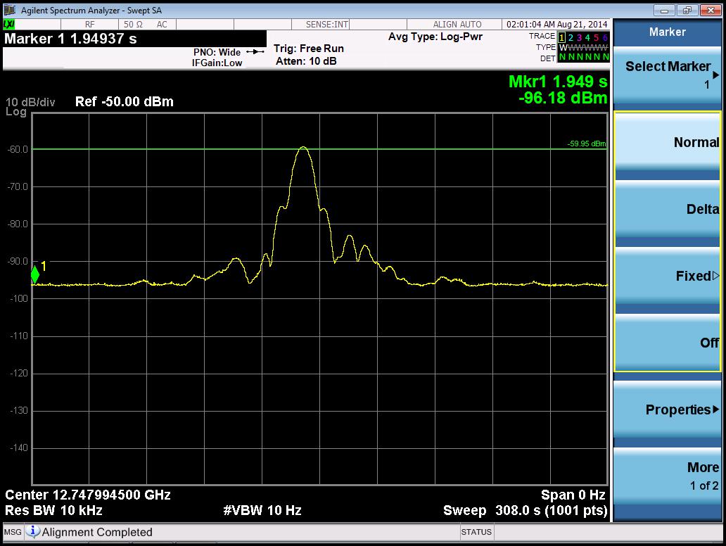
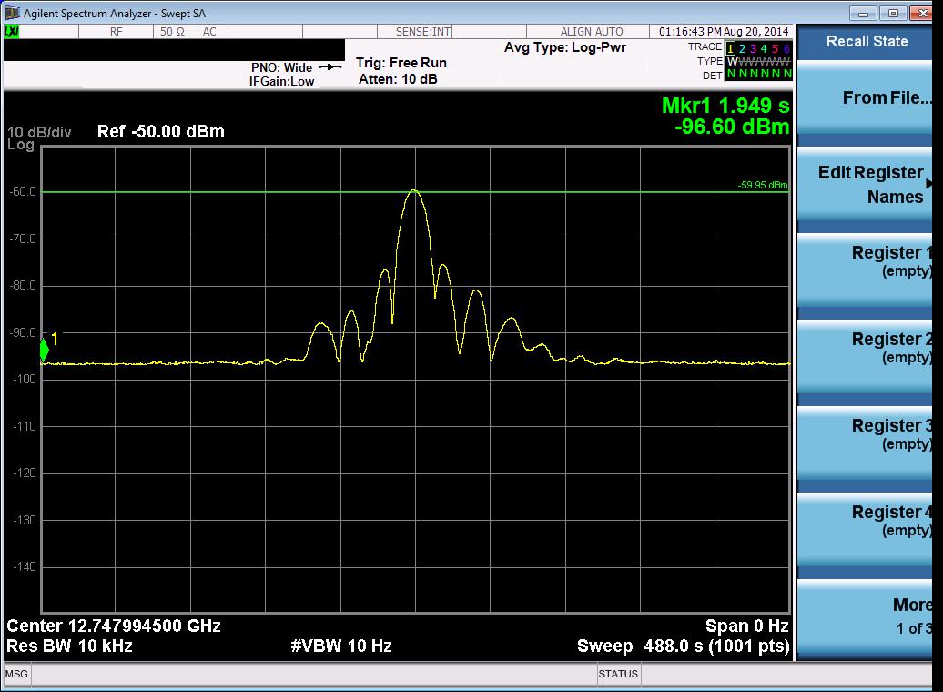
Antenna Testing Pattern

AZ TEST RESUIT

EL TEST RESUIT
Conclusion
Arabsat & STC 9M Earth Station Project starts from contract signed on November 5, 2013, through design review of Technical Proposal of Earth Station Project,equipment procurement, factory test, equipment shipment, on-site installation, on-site commissioning and test, antenna technical performance meet the requirement of the contract through joint effort by two parties. Equipment quantity and models also meet the contract requirement.

